A 748R Story
The Correction Factor
I've never had a dyno cell with inlet air heating capability, so I've noticed this winter that there is a considerable decrease in power with pre-heated inlet air into the dyno cell.
The 'World Class' dyno cell is a paint booth which is equipped with an inlet air heater. The heater is just a large natural gas element burning the oxygen in the incoming air. The heater comes on in 'Winter' mode but doesn't in 'Summer' mode. The landlord had to send an electrician over to 'jumper' the OATC (outside air temperature controller) so it didn't shut the fan off in 'Summer' mode when the outside air temp is below freezing.
The question is; is the change in power caused by depletion of the oxygen or the lowered inlet temperature.
The Dynojet instrument stack is located below the computer keyboard, off to the side of the inlet airflow. I've noticed that the dyno inlet temp displayed on the screen, doesn't respond very fast. Even though the temp/humidity sensor module has a small fan in it, it might be picking up heat from the modules below it.
No matter what the source of the power disparity, the correction factor doesn't change much because the indicated temperature doesn't change very much. Without an appropriate correction factor, the power numbers are inaccurate.
History
A local guy/racer decided he needed to race a 748R at the club level. That was in spite of the recommendations against it, by Todd Fisher and others who had an idea of the maintenance required to race one of these things.
The guy is cheap and capable of deluding himself, so it wasn't tuned (although he did stumble across a chip that I had made for another 'R') and the valve clearance wasn't ever checked or adjusted. Although, he assumed that it had been done by Todd who charged him $300 to prepare it for track use. He never really paid Todd, but he did give him a used car stereo?!??
The bike ended up on it's side the first or second time he raced it.
At the end of the '03 season he offered it for sale. I don't know where he advertised it, but Chris Topolniski of Calgary, took an interest in it. Chris has been using his 748 Strada and a Suzuki GSXR 600 on the track and decided to step up to the premium suspension components. The 748R is a good choice for that.
Chris knew of me from my friend Paul Shore who has a shop in Calgary (I sent a chip to Paul, that went into Chris's 748.) Chris wanted me to look it over and determine if he should buy it. I agreed to do the inspection, and it soon turned into an adjust and tune deal. I suggested that it would be a good use of time to modify the throttle bodies and extend the velocity stacks while that stuff was off, but it seemed kind of a waste with the horse-shit inlet ports. Chris decided to have me remove the heads and fix the ports.
When I had the manifolds off I discovered that the inlet ports had been fixed at the factory. The floor wasn't all screwed up like the other two I've seen. Excellent!!, I didn't have to remove the heads! The only reason I was relieved about that is that we have a lot of product testing to do before the end of January, and didn't know if I'd have the time.
I adjusted the valve clearance, replaced 1 opening rocker-arm, and didn't adjust the cam timing.
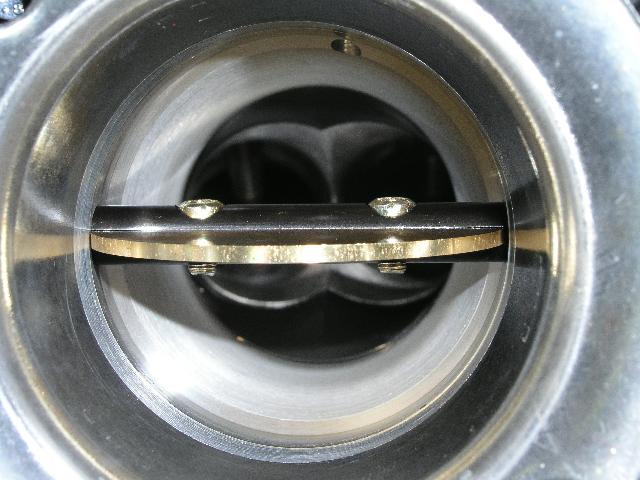
I tapered the restrictor portion of the throttle bodies and added a 13mm extension under the velocity stack.
You can see the narrow remainder of the original taper, it intersects the idle bypass hole at the top of the picture.
In this photo you can just see the 13mm spacer. There's a little chatter from the lathe.
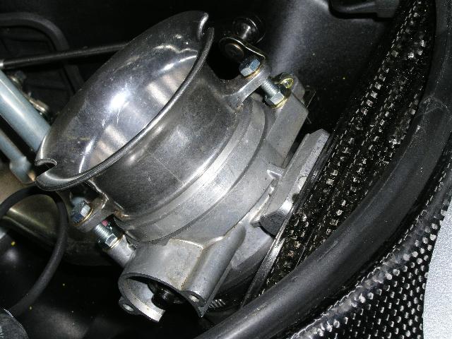
Below is a picture of the outside of the throttle body with the 13mm spacer in place.
The day after Christmas I started the mapping. I didn't expect it to take too long. I had done a few dyno runs with the fuel that was in the tank, but I didn't want to use the oxygen sensor, because I didn't know if the bike had leaded fuel in it. It made 111HP so I knew that the A/F ratio couldn't have been too far off.
The chart below shows the results at the start and at the end of the day.
Timing changes get the credit for a couple HP of the improvement, and testing with the dyno inlet air heater turned off gets credit for the rest.
I changed the 5800 RPM set-point on the fuel map to 5300 RPM in the software, so I could adjust the fuel in the dip at 5300. This is caused by the 46/50mm 1/2 system. Brad Black pointed that out in one of his reports, otherwise I might not have noticed. Being able to pin-point that feature really helps get a consistent A/F ratio chart.
As I finished (or thought I had finished) I was trying to get rid of that slight lean area at 10,500 RPM. My only excuse is that it was gaining power as I added fuel and I wanted to find out how much it would make. That is the point y'know!
I checked the specification sheet, which the FIM software generates, and found the the injectors were at 100% duty cycle before 9000RPM.
When one is trying to increase the fuel at elevated revs and the injectors have reached 100%, the chart of the fuel map starts to get bulged above the point where the injectors are maxxed, and the A/F ratio doesn't change.
The total time for two engine revolutions at 9000RPM is; 9000 / 60 = 150 rev/S=0.0066666 S/rev X 2 = 0.013333 S or 13.33mS.
That the map calls for 13.4mS.
At 9400, 12.766 mS is available and the map is requesting 12.9mS, at 10,600, 11.321 mS is available and the map requests 14.0mS. It'll never catch up at that rate.
So, what did I do? I smashed the pressure regulator so the pressure went up from 44.5 PSI to 53.5 PSI. The flow changes as the square root of the pressure difference. The pressure increase is 20.2%, so the flow increase is 1.09647 and the injector time change is the inverse of that or 0.912.
Also, I changed the entire map by -8.5% and proceeded.
As the chart below shows, the power didn't increase. In fact, the A/F ratio still goes lean at the top. I managed to increase the fuel a little at 8000 and 8400, but that wasn't enough to carry through to the top.
The WOT fuel was real close, but I had to re-adjust the trim pot. to richen the idle. This shows (at least, implies) that the fuel flow characteristics aren't completely linear with a pressure change.
Conclusions
This whole exercise illustrates the minimal improvement of modifying the stock pressure regulator. Dinking around with a few percent increase certainly doesn't create the kind of margin that I would like to see. It doesn't leave that +6% Zone 6-7 increase that is necessary for adjusting for ram-air.
From a practical standpoint, I have always questioned the impact of real pressure increases (5 bar) on fuel pump life.
Higher flow injectors, on the order of 20% more, would be the preferred solution. I have a Pico injector spec sheet from Weber, and the IWP 069 is the highest flow rating on the sheet. That doesn't mean that Weber hasn't produced one that flows more yet.
Brad asked about 996RS, which would be the US Superbike homologation piece of several years ago. With the IWP 069 injectors, 5 bar would support 145HP at the rear wheel, with no margin for upward adjustment. That would be somewhere around 155 at the transmission output shaft, where 'the Factory' measures with their dyno. Clearly they're using different injectors or very high fuel pressures.
The stock 996 injectors run out of fuel 3-5 HP higher than the IWP 069s.
I've run into this problem fairly often. I wonder how someone without the tools, like Duane's software, can even diagnose this type of problem.
When I attended the required Dynojet Power-Commander Center seminar in '95(?) I asked about the ability to view the map with which one is working. I was told that one doesn't need to know that, the only thing that matters is the final fuel result.
I never accepted that explanation because it feels like mucking about in the dark. This report illustrates why we need to have all the information.
I rest my case!